ESP-12E WiFi modul for Arduino


Pris:
kr. 45,00
Model:ESP8266-12
ISM 2.4GHz
PA +25dBm
802.11b/g/n
Warnings:
1.This module requires a 3.3 volt supply for VCC, and 3.3V logic.
2.It is not 5V tolant,Connect RX or TX on 5V Arduino will destroy this module.
3.You must use a logic level converter, or a 3.3V Arduino
4.The 3.3V supply on the Arduino Uno has inadequate current capabilit to power this
module.
5.You must provide a separate,higher 3.3V supply(about 300mA or better)
Package includes:
1/2/5/10PCS ESP8266 ESP-12E Wireless Remote Serial WIFI Transceiver Board Module


https://github.com/skule1/Alexa-controlled-kitchen-light
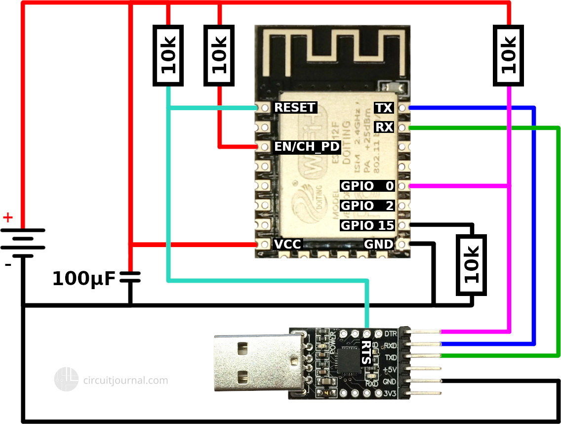
IMPORTANT! The 3.3V power output of the USB-to-serial adapter is too weak to run the ESP-12E / ESP-12F module. You need to use an external 3.3V power source.
Full (automatic reset) - if your USB-to-serial adapter has RTS output available, you can wire up fully automatic connections. It means that you can click "Upload" in the Arduino IDE, then it will automatically reset the ESP module and enter into programming mode. After a successful upload, it will reset again, and your program will run.
Simple (manual reset) - some simpler adapter modules do not bring the RTS signal out as an accessible output (even though the USB-to-serial chip on the board probably has it). In that case, you need to connect the GPIO_0 pin to the ground and then reset the device manually. After successful upload, you need to disconnect the GPIO_0 pin from the ground and reset again.
The ESP8266 has three different boot modes selected by the state of GPIO_15, GPIO_0, and GPIO_2 at start-up.
| MODE | GPIO_15 | GPIO_0 | GPIO_2 |
|---|---|---|---|
| SDIO (Boot SD Card) | 1 | x | x |
| UART (Upload Code) | 0 | 0 | x or 1 |
| FLASH (Normal Running) | 0 | x or 1 | x or 1 |
1. SDIO (Boot SD Card) - this mode is irrelevant for us. Since we never want to use it, we can connect the GPIO_15 to GND via a 10k resistor.
Note: technically, you could also connect the GPIO_15 directly to the ground without a resistor. But if you accidentally define GPIO_15 as output in your Arduino code and now set the pin to HIGH, it will create a short circuit and probably damage the microcontroller.
2. UART (Upload Code) - we need to activate this mode to upload new code. Both GPIO_15 and GPIO_0 pin need to be pulled down to the ground at the boot-up time. GPIO_2 may be left unconnected (or pulled up to 3.3V).
3. FLASH (Normal Running) - this mode is for running your code. GPIO_15 must be pulled to the ground, and GPIO_0 and GPIO_2 must be left either floating or pulled up to 3.3V.
The "chip enable" (EN/CH_PD) pin has to be pulled up to 3.3V. Otherwise, the ESP8266 will not run

ESP8266 ESP-01 WIFI Wireless Transceiver
Pris: kr. 65,00
ESP-WROOM 02
Pris: kr. 45,00
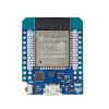
NodeMCU Lua ESP8266 modul
Pris: kr. 75,00
D1 mini PRO ESP8266 WiFi ext antenne
Pris: kr. 78,00
Arduino MEGA med ESP8266 WiFi
Pris: kr. 360,00
Arduino MEGA med ESP8266 WiFi
Pris: kr. 360,00