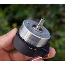
12V Nidec 24H055M020 BLDC Brushless Motor
Pris:
kr. 210,00
Description
We have test motor and feel that there are several points that buyers need to pay attention to:
1. The power supply connection to motor, should connect correctly.
If connected incorrectly, it will burn out the drive board.
Pay attention to the power supply polority.
2 . The input voltage can only be controlled between DC10V-13V,
which is relatively strict. If it exceeds this range, it seems that it cannot be started.
3 . The direction line is suspended as CW, and when it connect the positive pole, it is CCW.
However, if you want to select CCW, then the direction line should be connected to the starting line in parallel, with the starting line (blue line) being the slowest to conduct or the first to disconnect. Because if the direction line is connected to the power supply, the driver board inside seems to be working. We don't understand the reason.
4. The yellow line requires the input of a pulse frequency to start the motor,
which can only be started when the pulse frequency is between 16000HZ and 26000HZ.
According to our simple wiring method, power on the test machine and use pulse frequency to control the speed parameters as follows:
1000HZ 150rpm 40 MA
10000 HZ 1500rpm 68 MA
12000 HZ 1800rpm 75 MA
18000 HZ 2700rpm 96 MA
22000 HZ 3300rpm 108 MA
26000 HZ 3900rpm. 122 MA
From the data, it can be seen that this is a precise and controllable micro brushless motor.
When the pulse increases by 1000 Hz, the motor's speed increases by 150rpm, which is very precise.
As for the wiring method of the feedback line, we do not understand it, and our usage method is not completely correct.
We are an outsider in technology, so buyers should understand the technology themselves
and feel that it can be used before place order. We cannot provide further technical support.
Motor Parameter:
Outer diameter of motor: 41.9 MM
Motor height: 34 MM
Motor shaft diameter: 6 mm (with flat position of 4.5 mm)
Output shaft length: 16.5 MM
Motor weight: 118 grams
Voltage: DC12V
Maximum speed: 3900 RPM
Line length: 100 MM


According to our current understanding, the description is as follows:
Yellow line: PWM, pulse frequency 16000HZ-26000HZ
Blue line: start/stop, start when connected to the positive pole, and stop when disconnected.
White line: Electronic brake, release when suspended, brake when connected to GND.
Green Line: Direction. Turn to CW when suspended, and CCW when connected to the positive pole.
The 5th, 6th, 7th, and 8th pins are the four wires for feedback signals. We currently don't know how to use them, only know that the purple wire (8th wire) is also GND. The other three lines are just one with a voltage of+3.7V and the other with a signal output.
Black line: GND
Black line: GND
Red line:+12V (between 10V-13V)
Red line:+12V (between 10V-13V)
We also do not understand the correct usage of this motor. We connected the motor according to the above wiring method, and the motor can operate normally. However, as for the wiring of the feedback signal, we do not understand it. Moreover, our wiring method still has certain problems, as the pulse frequency suitable for speed regulation of this motor is between 1000HZ-26000HZ. For every increase in frequency of 1000 HZ, the motor's speed increases by 150 revolutions, which is very accurate, But we found during the machine test that when the frequency was below 16000 Hz, it was not possible to start according to our wiring method. We used the last positive electrode of the starting wire as the starting method, but only when the frequency was between 16000HZ-26000HZ can we effectively start. After startup, the frequency can be adjusted between 1000HZ-26000HZ, which can adjust the speed.
This is just a strange thing, it can start even when the input pulse is below 1000Hz, and it can start normally when the input frequency is between 16000HZ and 26000HZ. The intermediate pulse frequency (1100-16000HZ) will shake when starting, but it cannot start. As for the technical principle inside, we don't understand it

