A4988 Step motor driver


Pris:
kr. 35,00
Description:
Function and advantages
The low RDS (on) output
Automatic current attenuation pattern detection/choice
Mixed with slow current attenuation model
For low power dissipation synchronous rectifier
Internal UVLO
Cross current protection
3.3 and 5 V compatible logic power supply
Overheating shutdown circuit
Grounding short circuit protection
Load short circuit protection
Five optional step mode: full, 1/2, 1/4, 1/8 and 1/16
A4988 is a completely, micro step motor driver with built-in converter, easy to operate. The product can be in full, half, 1/4, 1/8 and 1/16 step mode operation bipolar stepper motor, the output driving performance can be up to 35 V and + / - 2 A. A4988 includes a fixed current regulator close time, the voltage stabilizer can work in a slow or mixed decay modes. The converter is the key to A4988 is easy to implement. As long as in the "step" input a pulse input, can produce microstep driving motor. Don't need to control the phase sequence table, high frequency line or complex interface programming. A4988 interface is very suitable for the application of complex microprocessor is unavailable or overload.
In micro step is running, the chopping control for A4988 can automatically select current attenuation mode (slow or mixed). In hybrid damping model, the initial setting for device in a part of the fixed stop time fast attenuation, and then the rest of the downtime slow attenuation. Mixing decaying current control scheme can reduce the motor can be heard the noise and increase the precision stepper and reduce power consumption. Provide internal synchronous rectifier control circuit, in order to improve the pulse width modulation (PWM) operation of the power consumption. Internal circuit protection includes: take off the overheating of lag, under-voltage lockout (UVLO) and crossover current protection. Don't need special electricity sorting.
A4988 QFN package (ES) surface installation is adopted, the size is 5 mm x 5 mm, nominal overall packaging height is 0.90 mm, with exposed hot plate to strengthen the function of heat dissipation. The encapsulation of lead-free packaging (suffix - T), with 100% fog box tin plating pin.
https://www.pololu.com/product/1182
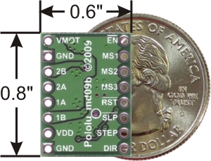
This breakout board for Allegro’s A4988 microstepping bipolar stepper motor driver features adjustable current limiting, over-current and over-temperature protection, and five different microstep resolutions (down to 1/16-step). It operates from 8 V to 35 V and can deliver up to approximately 1 A per phase without a heat sink or forced air flow (it is rated for 2 A per coil with sufficient additional cooling). This board ships with 0.1″ male header pins included but not soldered in.
Alternatives available with variations in these parameter(s): header pins soldered? bulk packaged? Select variant…
![]() Compare all products in A4988 Stepper Motor Driver Carriers.
Compare all products in A4988 Stepper Motor Driver Carriers.
|
Description |
|
|
|
|
|
|
|
|
|
A4983/A4988 stepper motor driver carrier with dimensions. |
Overview
This product is a carrier board or breakout board for Allegro’s A4988 DMOS Microstepping Driver with Translator and Overcurrent Protection; we therefore recommend careful reading of the A4988 datasheet (1MB pdf) before using this product. This stepper motor driver lets you control one bipolar stepper motor at up to 2 A output current per coil (see the Power Dissipation Considerations section below for more information). Here are some of the driver’s key features:
- Simple step and direction control interface
- Five different step resolutions: full-step, half-step, quarter-step, eighth-step, and sixteenth-step
- Adjustable current control lets you set the maximum current output with a potentiometer, which lets you use voltages above your stepper motor’s rated voltage to achieve higher step rates
- Intelligent chopping control that automatically selects the correct current decay mode (fast decay or slow decay)
- Over-temperature thermal shutdown, under-voltage lockout, and crossover-current protection
- Short-to-ground and shorted-load protection
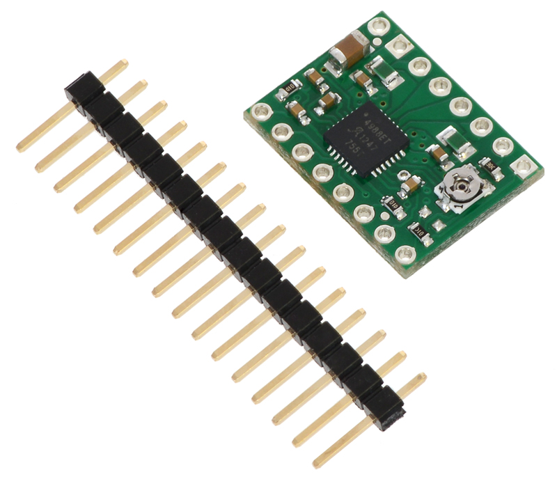
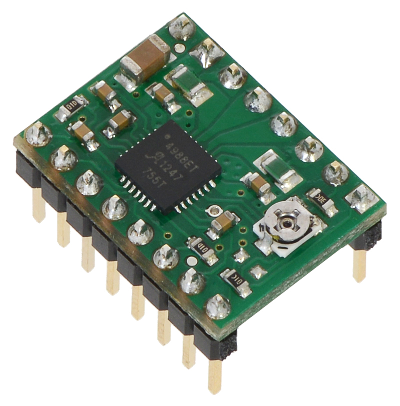
This product ships with all surface-mount components—including the A4988 driver IC—installed as shown in the product picture.
This product ships individually packaged with 0.1″ male header pins included but not soldered in; we also carry a version with male header pins already soldered in. For customers interested in higher volumes at lower unit costs, we offer a bulk-packaged version without header pins and a bulk-packaged version with header pins installed.
Note that we carry several stepper motor drivers that can be used as alternatives for this module (and drop-in replacements in many applications):
- The Black Edition A4988 stepper motor driver carrier is available with approximately 20% better performance; except for thermal characteristics, the Black Edition and this (green) board are interchangeable.
- The MP6500 carrier can deliver up to 1.5 A per phase (continuous) without a heat sink and is available in two versions, one with a pot for controlling the current limit and one with digital current limit control for dynamic current limit adjustment by a microcontroller.
- The DRV8825 carrier offers approximately 50% better performance over a wider voltage range and has a few additional features.
- The DRV8834 carrier works with motor supply voltages as low as 2.5 V, making it suitable for low-voltage applications.
- The DRV8880 carrier offers dynamically scalable current limiting and “AutoTune”, which automatically selects the decay mode each PWM cycle for optimal current regulation performance based on factors like the motor winding resistance and inductance and the motor’s dynamic speed and load.
We also sell a larger version of the A4988 carrier that has reverse power protection on the main power input and built-in 5 V and 3.3 V voltage regulators that eliminate the need for separate logic and motor supplies.
Some unipolar stepper motors (e.g. those with six or eight leads) can be controlled by this driver as bipolar stepper motors. For more information, please see the frequently asked questions. Unipolar motors with five leads cannot be used with this driver.
Included hardware
The A4988 stepper motor driver carrier comes with one 1×16-pin breakaway 0.1" male header. The headers can be soldered in for use with solderless breadboards or 0.1" female connectors. You can also solder your motor leads and other connections directly to the board. (A version of this board with headers already installed is also available.)
|
|
Using the driver
|
|
|
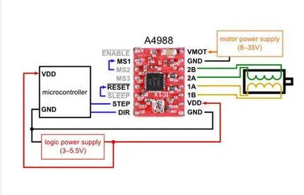
Minimal wiring diagram for connecting a microcontroller to an A4988 stepper motor driver carrier (full-step mode). |

Power connections
The driver requires a logic supply voltage (3 – 5.5 V) to be connected across the VDD and GND pins and a motor supply voltage (8 – 35 V) to be connected across VMOT and GND. These supplies should have appropriate decoupling capacitors close to the board, and they should be capable of delivering the expected currents (peaks up to 4 A for the motor supply).
Warning: This carrier board uses low-ESR ceramic capacitors, which makes it susceptible to destructive LC voltage spikes, especially when using power leads longer than a few inches. Under the right conditions, these spikes can exceed the 35 V maximum voltage rating for the A4988 and permanently damage the board, even when the motor supply voltage is as low as 12 V. One way to protect the driver from such spikes is to put a large (at least 47 µF) electrolytic capacitor across motor power (VMOT) and ground somewhere close to the board.
Motor connections
Four, six, and eight-wire stepper motors can be driven by the A4988 if they are properly connected; a FAQ answer explains the proper wirings in detail.
Warning: Connecting or disconnecting a stepper motor while the driver is powered can destroy the driver. (More generally, rewiring anything while it is powered is asking for trouble.)
Step (and microstep) size
Stepper motors typically have a step size specification (e.g. 1.8° or 200 steps per revolution), which applies to full steps. A microstepping driver such as the A4988 allows higher resolutions by allowing intermediate step locations, which are achieved by energizing the coils with intermediate current levels. For instance, driving a motor in quarter-step mode will give the 200-step-per-revolution motor 800 microsteps per revolution by using four different current levels.
The resolution (step size) selector inputs (MS1, MS2, and MS3) enable selection from the five step resolutions according to the table below. MS1 and MS3 have internal 100kΩ pull-down resistors and MS2 has an internal 50kΩ pull-down resistor, so leaving these three microstep selection pins disconnected results in full-step mode. For the microstep modes to function correctly, the current limit must be set low enough (see below) so that current limiting gets engaged. Otherwise, the intermediate current levels will not be correctly maintained, and the motor will skip microsteps.
|
MS1 |
MS2 |
MS3 |
Microstep Resolution |
|
Low |
Low |
Low |
Full step |
|
High |
Low |
Low |
Half step |
|
Low |
High |
Low |
Quarter step |
|
High |
High |
Low |
Eighth step |
|
High |
High |
High |
Sixteenth step |
Control inputs
Each pulse to the STEP input corresponds to one microstep of the stepper motor in the direction selected by the DIR pin. Note that the STEP and DIR pins are not pulled to any particular voltage internally, so you should not leave either of these pins floating in your application. If you just want rotation in a single direction, you can tie DIR directly to VCC or GND. The chip has three different inputs for controlling its many power states: RST, SLP, and EN. For details about these power states, see the datasheet. Please note that the RST pin is floating; if you are not using the pin, you can connect it to the adjacent SLP pin on the PCB to bring it high and enable the board.
Current limiting
One way to maximize stepper motor performance is to use as high of a voltage as is practical for your application. In particular, increasing the voltage generally allows for higher step rates and stepping torque since the current can change more quickly in the coils after each step. However, in order to safely use voltages above the rated voltage of a stepper motor, the coil current must be actively limited to keep it from exceeding the motor’s rated current.
The A4988 supports such active current limiting, and the trimmer potentiometer on the board can be used to set the current limit. One way to set the current limit is to put the driver into full-step mode and measure the current running through a single motor coil while adjusting the current limit potentiometer. This should be done with the motor holding a fixed position (i.e. without clocking the STEP input). Note that the current you are measuring is only 70% of the actual current limit setting, since both coils are always on and limited to this value in full-step mode, so if you later enable microstepping modes, the current through the coils will be able to exceed this measured full-step current by 40% (1/0.7) on certain steps; please take this into account when using this method to set the current limit. Also, note that you will need to perform this adjustment again if you ever change the logic voltage, Vdd, since the reference voltage that sets the current limit is a function of Vdd.
Note: The coil current can be very different from the power supply current, so you should not use the current measured at the power supply to set the current limit. The appropriate place to put your current meter is in series with one of your stepper motor coils.
Another way to set the current limit is to calculate the reference voltage that corresponds to your desired current limit and then adjust the current limit potentiometer until you measure that voltage on the VREF pin. The VREF pin voltage is accessible on a via that is circled on the bottom silkscreen of the circuit board. The current limit, IMAX, relates to the reference voltage as follows:
IMAX=VREF8⋅RCSIMAX=VREF8⋅RCS
or, rearranged to solve for VREF:
VREF=8⋅IMAX⋅RCSVREF=8⋅IMAX⋅RCS
RCS is the current sense resistance; original versions of this board used 0.050 Ω current sense resistors, but we switched to using 0.068 Ω current sense resistors in January 2017, which makes more of the adjustment potentiometer’s range useful. The following picture shows how to identify which current sense resistors your board has:
|
|
|
Identification of original 50 mΩ sense resistors (left) and 68 mΩ sense resistors (right) introduced in January 2017. |
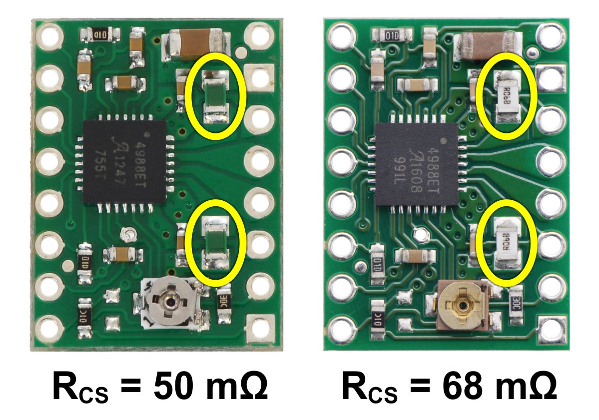
So, for example, if you want to set the current limit to 1 A and you have a board with 68 mΩ sense resistors, you would set VREF to 540 mV. Doing this ensures that even though the current through each coil changes from step to step, the magnitude of the current vector in the stepper motor stays constant at 1 A:
I2COIL1+I2COIL2−−−−−−−−−−−−−√=IMAX=1AICOIL12+ICOIL22=IMAX=1A
If you instead want the current through each coil to be 1 A in full-step mode, you would need to set the current limit to be 40% higher, or 1.4 A, since the coils are limited to approximately 70% of the set current limit in full-step mode (the equation above shows why this is the case). To do this with a board with 68 mΩ sense resistors, you would set VREF to 770 mV.
Power dissipation considerations
The A4988 driver IC has a maximum current rating of 2 A per coil, but the actual current you can deliver depends on how well you can keep the IC cool. The carrier’s printed circuit board is designed to draw heat out of the IC, but to supply more than approximately 1 A per coil, a heat sink or other cooling method is required.
This product can get hot enough to burn you long before the chip overheats. Take care when handling this product and other components connected to it.
Please note that measuring the current draw at the power supply will generally not provide an accurate measure of the coil current. Since the input voltage to the driver can be significantly higher than the coil voltage, the measured current on the power supply can be quite a bit lower than the coil current (the driver and coil basically act like a switching step-down power supply). Also, if the supply voltage is very high compared to what the motor needs to achieve the set current, the duty cycle will be very low, which also leads to significant differences between average and RMS currents.
Schematic diagram
|
|
|
Schematic diagram of the A4988 stepper motor driver carrier (both green and black editions). |

Note: This board is a drop-in replacement for our original (and now discontinued) A4983 stepper motor driver carrier. The newer A4988 offers overcurrent protection and has an internal 100k pull-down on the MS1 microstep selection pin, but it is otherwise virtually identical to the A4983.
Description:
1. A4988 Stepper Motor Driver
This product is a breakout board for Allegro’s A4988 DMOS Microstepping Driver with Translator and Overcurrent Protection; please read the A4988 datasheet carefully before using this product. This stepper motor driver lets you to operate bipolar stepper motors in full-, half-, quarter-, eighth-, and sixteenth-step modes, with an output drive capacity of up to 35 V and 2 A.
The translator is the key to the easy implementation of the A4988. Simply inputting one pulse on the STEP input drives the motor one microstep. There are no phase sequence tables, high frequency control lines, or complex interfaces to program.The A4988 interface is an ideal fit for applications where a complex microprocessor is unavailable or is overburdened.
Connecting or disconnecting a stepper motor while the driver is powered can destroy the driver(More generally, rewiring anything while it is powered isasking for trouble).
Features:
1.Maximum output current is 1A
2.Simple step and direction control interface
3.Five different step resolutions: full-step, half-step, quarter-step, eighth-step, and sixteenth-step
4.Adjustable current control lets you set the maximum current output with a potentiometer, which lets you use voltages above your stepper motor’s rated voltage toachieve higher step rates
5.Intelligent chopping control that automatically selects the correct current decay mode (fast decay or slow decay)
6.Over-temperature thermal shutdown, under-voltage lockout, and crossover-current protection
7.Short-to-ground and shorted-load protection
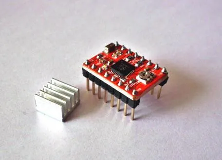
2. Heatsink
This 9x10x5mm heatsink, purchased for use with the pololu A4988 drivers, despite their tiny size they are still very large when placed on the driver, may require machining to fit on the Pololu drivers but if careful with soldering and it clears the SMD resistors I don't see the need for any modification.
Pls note it doesn't come with adhesive
Note (other colors Green color, Please leave a messages to tell which color you want after you placed the order
if not remark, default is Red)
Package List:
50 x A4988 Stepper Motor Driver
50 x Heatsink
![]()

https://github.com/laurb9/StepperDriver
StepperDriver
A4988, DRV8825, DRV8834, DRV8880 and generic two-pin stepper motor driver library. Features:
- Constant speed mode (low rpms)
- Linear (accelerated) speed mode, with separate acceleration and deceleration settings.
- Non-blocking mode (yields back to caller after each pulse)
- Early brake / increase runtime in non-blocking mode
Hardware currently supported:
- DRV8834 Low-Voltage Stepper Motor Driver up to 1:32
- A4988 Stepper Motor Driver up to 1:16
- DRV8825 up to 1:32
- DRV8880 up to 1:16, with current/torque control
- any other 2-pin stepper via DIR and STEP pins, microstepping up to 1:128 externally set
Microstepping
The library can set microstepping and generate the signals for each of the support driver boards.
High RPM plus high microstep combinations may not work correctly on slower MCUs, there is a maximum speed achieveable for each board, especially with acceleration on multiple motors at the same time.
Motors
- 4-wire bipolar stepper motor or
- some 6-wire unipolar in 4-wire configuration (leaving centers out) or
- 28BYJ-48 (commonly available) with a small modification (search for "convert 28byj-48 to 4-wire").
Connections
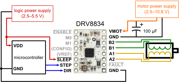
Minimal configuration from Pololu DRV8834 page:
Wiring
This is suggested wiring for running the examples unmodified. All the pins below can be changed.
-
Arduino to driver board:
- DIR - D8
- STEP - D9
- GND - Arduino GND
- GND - Motor power GND
- VMOT - Motor power (check driver-specific voltage range)
- A4988/DRV8825 microstep control
- MS1/MODE0 - D10
- MS2/MODE1 - D11
- MS3/MODE2 - D12
- DRV8834/DRV8880 microstep control
- M0 - D10
- M1 - D11
- ~SLEEP (optional) D13
-
driver board to motor (this varies from motor to motor, check motor coils schematic).
-
100uF capacitor between GND - VMOT
-
Make sure to set the max current on the driver board to the motor limit (see below).
-
Have a motor power supply that can deliver that current.
-
Make sure the motor power supply voltage is within the range supported by the driver board.
Set Max Current
The max current is set via the potentiometer on board. Turn it while measuring voltage at the passthrough next to it. The formula is V = I5R where I=max current, R=current sense resistor installed onboard
- DRV8834 or DRV8825 Pololu boards, R=0.1 and V = 0.5 * max current(A). For example, for 1A you will set it to 0.5V.
For latest info, see the Pololu board information pages.
Code
See the BasicStepperDriver example for a generic driver that should work with any board supporting the DIR/STEP indexing mode.
The Microstepping example works with a DRV8834 board.
For example, to show what is possible, here is the ClockStepper example that moves a stepper motor like the seconds hand of a watch:
#include <Arduino.h>
#include "A4988.h"

// using a 200-step motor (most common)
#define MOTOR_STEPS 200
// configure the pins connected
#define DIR 8
#define STEP 9
#define MS1 10
#define MS2 11
#define MS3 12
A4988 stepper(MOTOR_STEPS, DIR, STEP, MS1, MS2, MS3);

void setup() {
    // Set target motor RPM to 1RPM and microstepping to 1 (full step mode)
    stepper.begin(1, 1);
}

void loop() {
    // Tell motor to rotate 360 degrees. That's it.
    stepper.rotate(360);
}
Hardware
- Arduino-compatible board
- A stepper motor driver, for example DRV8834, DRV8825, DRV8824, A4988.
- A Stepper Motor.
- 1 x 100uF capacitor


TB6612FNG Dual DC Stepper Motor Drive Controller - TB432A1
Pris: kr. 45,00
DRV8825 Stepper Motor Driver Module
Pris: kr. 25,00
TB6612FNG 5V Dual Motor Driver Module PW - TB724A3M
Pris: kr. 55,00
TMC2208 V3.0 Stepper Motor Driver
Pris: kr. 150,00
TMC2209 V2.0 Stepper Motor Driver
Pris: kr. 190,00
CNC Expansion Shield V3
Pris: kr. 220,00
SKR v1.3 3D 32bit printer kontroller
Ring/SMS etter pris: 91166668